Known Issue
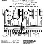
A few Sherline CNC systems manufactured before 4/05 will show a problem when turning on power to the built-in driver box. The light will not glow fully bright red, and power will not come up on all four drivers. This is not an issue on most boards, but if you have a system that exhibits this problem, the following change of position of a single resistor and changing a chip on the circuit board will solve the problem. Contact Sherline for a new chip and resistor if you experience this problem. To date, we know of only 4 or 5 cases of this problem. All boards after 4/1/05 were changed to eliminate the possibility of this problem.
If you do not feel you want to take on this repair, you can call for an RMA number, return your driver board/power supply or the whole computer, and Sherline will make the repair under warranty.
Relocating or changing the R9 resistor
- Turn off the computer and unplug it from the wall.
- Open the side of the computer case and unplug the four X, Y, Z, and A axis stepper motor cables from the left side of the driver circuit board. Then unplug the 25-pin parallel cable from the right side of the board.
- Unplug the LED light cable (above the on/off switch) from the side of the computer case you just removed.
- Disconnect the wire plug on the black wire that goes to the on/off switch on the side of the computer case.
- Using a screwdriver, disconnect the screw on the closest terminal on the right side of the power supply and remove the (black) power wire.
- In the same manner, disconnect the next two wires (white and green) from the terminals on the power supply.
- From the bottom of the computer case, remove the four screws that secure the power supply and remove the power supply and circuit board unit from the computer.
- Remove the three white plastic nuts that secure the circuit board to the power supply and lift off the circuit board.
- Observe the photos and diagrams in the links below and locate the R9 resistor. On the bottom of the board, scratch through the trace as shown to disconnect one end of the resistor from the board.
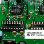
- On top of the board, snip the connector on the left side of the resistor (the side closest to the edge of the board) as close to the board as possible. This should leave enough wire for it to be bent and re-soldered to the new terminal point shown in the photos and diagram. If you prefer, you can also remove the resistor entirely and reinstall a new 330 Ohm, 1/8 Watt resistor in the location shown.
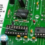
- Using a small flat-bladed screwdriver, pry up and remove the IC chip closest to the left side of the board and just below the R9 resistor (see photo 2 below) and reinstall the new chip provided. This new chip is reprogrammed to limit power to the other motors during start-up to prevent a sudden overload. Make sure all legs of the chip are straight and are going into their proper receptacles before pushing it down. Please return the old chip to Sherline so we can get credit for it from the manufacturer.
- Reinstall the board to the power supply and the power supply to the computer in reverse order.
Click on any image and use the “forward” and “previous” arrows to view enlarged images. To end the slideshow, just click in the gray area.
-
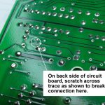
- On bottom of circuit board, scratch across the trace as shown to break its continuity.
-
- Find the existing resistor shown and snip the wire where it is soldered to the board on the right.
-
- Pivot the resistor (or install a new one) and solder it into the new location as shown.
-
- Top side of the circuit board to see where to relocate the resistor.
-
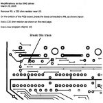
- Bottom side of the circuit board to see where to break the trace.