Click the questions below to find the answers.
GETTING STARTED
-
I notice that there are Metric and Inch versions of Sherline’s DRO. Can the DRO convert Inch to Metric or vice versa?
-
I notice the X-axis reads “backwards.” Is it possible to change this?
-
I moved the display to the top of my speed control housing as suggested in your tips section, but the display contrast is worse, and it’s hard to see. Can this be adjusted?
-
I’d like to modify the DRO software so it will do “X.” Can I get the internal software that it runs?
-
On most full-sized DROs, I can enter values on a keypad to set the datum. On the Sherline DRO, I can only zero an axis. How can I get the DRO to read out the position relative to my part?
-
I’m having trouble getting consistent readings on one or more of my DRO axes. Is there a way to fix this issue?
ADDRESSING BACKLASH
-
How do I remove backlash from the DRO assembly?
-
I’ve zeroed out my Z-axis by moving the crosslide against the headstock hard stop, but I get an error on my DRO reading when I move the crosslide out and back in. How do I fix this?
-
I am concerned about the accuracy of Sherline’s DRO since it only measures handwheel turns rather than the actual table position. What about backlash?
-
I don’t understand the whole DRO backlash compensation feature. When I enter values, it doesn’t seem like anything changes.
DRO on CNC
-
If I have a CNC machine and I mount the encoders on the back of the motor, can the DRO keep up?
-
I noticed that when I move my axis on my CNC machine rapidly, the display freezes on the DRO until I come to the end of the move. Is the DRO losing steps while the axis is moving at a rapid feed rate? Is the position reading at the end of a rapid move accurate?
ENCODER WIRING
-
How are the encoders wired? Circuit Diagrams for Position Sensors
-
Can I extend the encoder wires or put switches on them etc.?
-
Can I “Y” two sets of encoders (lathe and mill) together and connect them to one readout?
-
Is there a point in the circuit where I can tap off serial data, RS-232, etc. to input to my computer?
-
Can the Sherline encoders and sensors be used with other systems?
-
What are the specs for the power connector on the DRO?
GETTING STARTED
I notice that there are Metric and Inch versions of Sherline’s DRO. Can the DRO convert Inch to Metric or vice versa?
Yes! Originally, and for many years, the DRO just read handwheel rotations based on the leadscrew pitch installed in the machine, which was set during installation. With the addition of the 2 mm ball screws with no inch equivalent, this became an issue for some users. In August 2021, the DRO operation was modified to do metric or inch conversions – providing readings in the units required with any leadscrew installed. DROs shipping after August 2021 include this feature, and older units can be upgraded for a fee (Contact Sherline for details).
Back to DRO FAQ Index
I notice the X-axis reads “backwards.” Is it possible to change this?
Yes, reversing any axis is simple if you’re handy with a soldering iron. You reverse the black and green wires at the encoders. Details are included in the latest revision of the manual on the website.
CLICK HERE for instructions (go to page 5)
Back to DRO FAQ Index
I moved the display to the top of my speed control housing as suggested in your tips section, but the display contrast is worse, and it’s hard to see. Can this be adjusted?
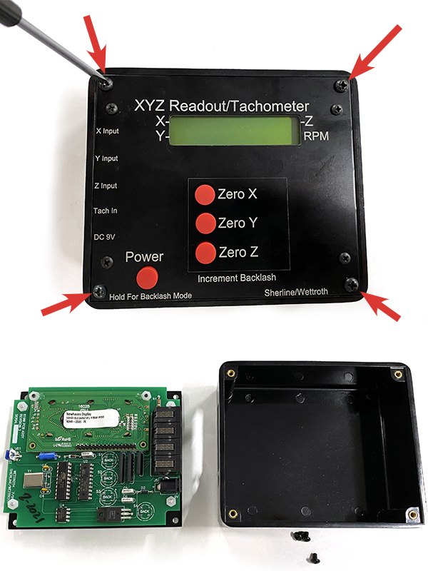
Yes, there is a contrast potentiometer on the board on the opposite side of the board from all the connections.
Unscrew the four corner screws that hold the DRO faceplate and control onto the housing (see photo for reference).
Adjust the potentiometer slowly while looking at the display in the position you’ll use it.
Back to DRO FAQ Index
I’d like to modify the DRO software so it will do “X.” Can I get the internal software that it runs?
No, we’re sorry this isn’t possible.
Back to DRO FAQ Index
On most full-sized DROs, I can enter values on a keypad to set the datum. On the Sherline DRO, I can only zero an axis. How can I get the DRO to read out the position relative to my part?
There is no keyboard, but if you’re clever, you can enter any datum you like. On the lathe, for example: take a skim cut on your part to establish a position and zero the DRO. Measure the part diameter accurately. Advance the axis half this distance and zero the DRO again. The readings are now referenced to the center of the part. Similarly, on the mill: edge find on the part. Zero the DRO. Advance half of the edge finder diameter and zero the DRO, and your readings are now referenced to the edge of your part. Once you establish a datum, you can move it around this way. This is really what the keypad is doing on a full-sized DRO – it’s simulating a motion and making it “zero.”
Back to DRO FAQ Index
I’m having trouble getting consistent readings on one or more of my DRO axes. Is there a way to fix this issue?
On occasion, there are times when you may experience that your DRO is missing steps and you have issues with a DRO axis lacking repeatability, i.e., coming back to a known position and providing erroneous results.
These problems are usually due to encoder issues, but you can quickly rule out the readout box by swapping inputs and trying the problem encoder on a different input.
For a complete list of encoder troubleshooting steps, CLICK HERE.
Back to DRO FAQ Index
ADDRESSING BACKLASH
How do I remove backlash from the DRO assembly?
The following links are instructions for assembling your DRO handwheel on your Sherline machine. With proper assembly, you will be able to reduce the backlash in your machine to .002″ or less.
Z-axis Lathe PDF instructions: DRO Backlash Assembly
Mill DRO PDF instructions: Mill Digital Readout
Lathe DRO PDF instructions: Lathe Digital Readout
DRO Backlash Adjustment Video instructions: Backlash Adjustment
Back to DRO FAQ Index
I’ve zeroed out my Z-axis by moving the crosslide against the headstock hard stop, but I get an error on my DRO reading when I move the crosslide out and back in. How do I fix this?
There are three possible reasons for this.
-
- You may have excessive backlash.
- There may be an error in the DRO handwheel assembly.
- The DRO optical sensor may be worn.
CLICK HERE to view the detailed PDF instructions on troubleshooting backlash on a Sherline DRO Lathe.
Back to DRO FAQ Index
I am concerned about the accuracy of Sherline’s DRO since it only measures handwheel turns rather than actual table position. What about backlash?
Sherline machines were used with great accuracy with just handwheels for many years before the DRO. The DRO is a convenience and is as accurate as the leadscrews, which are very good. Remember that the most accurate measuring instrument for most machinists is the micrometer, which also relies on the turns of a leadscrew!
The DRO measures rotations of the handwheels to an effective accuracy of 1/100 of a rotation. If the encoder wheels are perfect, i.e., no flash, perfect geometry of tooth width to open slot width, and the runout and placement of the light sensors are perfect, you would expect that each 100th turn would be split in half and make the transition in the exact leading or trailing edge of a gap or tooth. Because of all the vagaries of all the stack up, this transition can happen anywhere in the interval; it seems to be about 30-70% of an interval. This isn’t really an accuracy issue; it’s a minimum-resolution issue. You can’t depend on fractions of a 1/100th, but you can depend on each 100th. This is similar to trying to split thousandths on a handwheel – it’s better than nothing but you’re interpolating.
See the next FAQ entry for details.
Back to DRO FAQ Index
I don’t understand the whole DRO backlash compensation feature. When I enter values, it doesn’t seem like anything changes.
The backlash compensation operation is subtle and can be ignored if you always dial values in the same direction, which is a good practice anyway. Backlash represents the “slop” in a thread when the direction is reversed. The backlash feature holds the last displayed value on the display until a motion greater than the backlash is made. If you watch closely, you’ll see that the display doesn’t change until you exceed the backlash, then it follows – this compensates for the slop. This is the same thing that you’re doing with feel when you dial in a value, then reverse direction a bit and dial to the final value. The backlash feature doesn’t have to be used if you find it confusing or distracting. Just leave the values at zero and remember always to load the leadscrew with the dial.
Back to DRO FAQ Index
DRO on CNC
If I have a CNC machine and I mount the encoders on the back of the motor, can the DRO keep up?
Yes, no problem. This has been tested at very high speeds.
See the next FAQ entry for details.
Back to DRO FAQ Index
I noticed that when I move my axis on my CNC machine rapidly, the display freezes on the DRO until I come to the end of the move. Is the DRO losing steps while the axis is moving at a rapid feed rate? Is the position reading at the end of a rapid move accurate?
At high speeds, you may see the DRO display freeze during fast moves but it will update after the move is complete. It won’t lose steps at any usable rate. The DRO looks for changes in the encoder very often if it’s in the middle of a calculation to display a new value and it senses a change in the encoder, it just aborts the display task and captures the new data so it won’t miss a step. At very high move rates, this causes the display to freeze, but the DRO is capturing all the moves perfectly. As soon as the movement slows down enough to do the display formatting – the display will update in real-time.
The limitation is driven mostly by how fast you can put characters on the display. It takes about 40 microseconds per character, and writing a sign, decimal point, value, and some spaces take about 400 microseconds for the display. There is also a bit of time spent formatting the display. This adds up to about 1 millisecond total to give you a best-case display rate of <1000/second. The DRO gets close to this theoretical value.
Mode Displays
Native Modes
In “native” modes, where the displayed units are the same as the leadscrew units – the unit can measure and display readings up to about 900 readings per second. These are modes 1, 2, and 6.
| Mode | Leadscrew Units | Display | Travel Speed |
|---|---|---|---|
| 1 | Leadscrew inch (05″/turn) | inch | 27″/min |
| 2 | Leadscrew mm (1 mm/turn) | mm | 550 mm/min |
| 6 | Ball screw mm (2 mm/turn) | mm | 850 mm/min |
The speeds in the table represent the travel speed at which “freezes” will occur. This is governed by the basic reading speed of about 900/second modified by the leadscrew pitch and a few other small technical details.
Non-Native Modes
In “non-native” modes like 3, 4, and 5, the raw units are measured and then have to be converted to the desired units. For metric to inch, this involves dividing by 25.4. For inch to metric, you multiply by 25.4. This math is done in a very optimized way but still takes a bit of time, which is about a millisecond. This varies a bit depending on the specific mode but it makes the rate about 350 to 500 readings per second.
| Mode | Leadscrew Units | Display | Travel Speed |
|---|---|---|---|
| 3 | Ball screw mm (2 mm/turn) | inch | 24″/min |
| 4 | Leadscrew inch (05″/turn) | mm | 330 mm/min |
| 5 | Leadscrew mm (1 mm/turn) | inch | 8″/min |
Overall, the travel speeds in the two preceding tables are the speeds at which the display will appear to freeze. These are probably good limits for a CNC machine of this size. The rates at which the DRO will miss steps are about 10x higher than these speeds. Though speeds higher than those listed in the tables are possible, and the DRO will register them correctly, they’re not appropriate even for rapid (non-cutting) movements for the Sherline. High-speed movements will create excessive wear on the machine.
Back to DRO FAQ Index
ENCODER WIRING
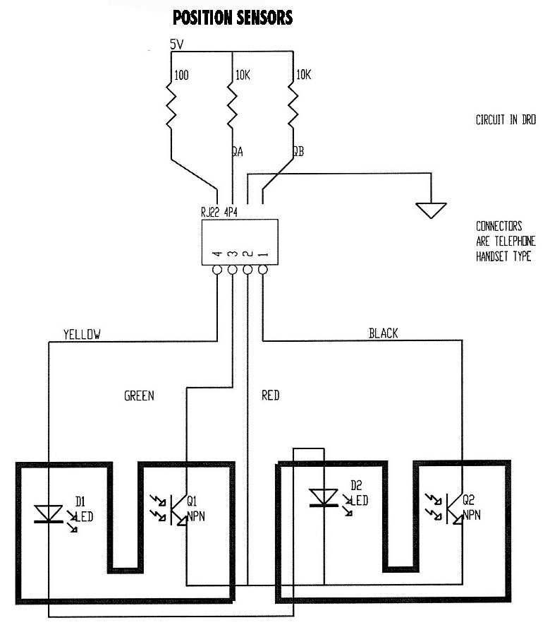
How are the encoders wired? See the circuit diagram below.

Can I extend the encoder wires or put switches on them etc.?
Yes. Keep the length to 10 feet maximum for reliable operation. Switches in the lines are no problem.
Back to DRO FAQ Index
Can I “Y” two sets of encoders (lathe and mill) together and connect them to one readout?
No, this won’t work; you’ll have to remove them and swap them.
Back to DRO FAQ Index
Is there a point in the circuit where I can tap off serial data, RS-232, etc. to input to my computer?
No, there isn’t such a point, and it wouldn’t be possible to do with the existing design.
Back to DRO FAQ Index
Can the Sherline encoders and sensors be used with other systems?
Probably, although we can’t give you much support beyond what is already offered in the instructions. The circuit diagrams attached have the components that are on the DRO side of the circuit for the encoders. They are programmed to be used with either a 20 thread per inch, a 1 mm pitch, or a 2 mm pitch leadscrew. Other pitch leadscrews will not yield correct numbers.
Back to DRO FAQ Index
What are the specs for the power connector on the DRO?
It’s a barrel connector with a 5.5mm OD and a 2.1mm ID. The center is positive 9V. The unit draws about 60 milliamps.
Back to DRO FAQ Index